Single Line Drawing Electrical : Flowtronix (Pvt.) Ltd. - Electrical, Instrumentation and ... / How to draw hvac single line diagram.. See more ideas about single line diagram, line diagram, electricity. This can be used by architects and engineers. The recently added movie on the cadline community entitled producing single line diagrams shows you how. Then the drawing can be imported, and partially exploded so it becomes revit drafting lines. This is never observed in static electricity.
Single line diagram is the representation of a power system using the simple symbol for each component. 1 electrical outlines and different kinds of drawings. This can be used by architects and engineers. This enables the user to place two different representations down of the same component. Typical electrical drawing symbols and.
Simplified Drawings: Electrical Distribution Drawings ... from cdn.allthingsnuclear.org The recently added movie on the cadline community entitled producing single line diagrams shows you how. A single line can show all or part of a system. Draw circuits represented by lines. All electrical schematics diagrams shall be stored in the cern drawing directory (cdd) with the relevant descriptive information and identified by a unique drawing number defined in. Electrical elements such as circuit breakers, transformers, capacitors, bus bars, and conductors are shown by standardized schematic symbols.instead of representing each of three phases with a separate line or terminal. Such a simplified diagram of an electric power system is called single line diagram of electrical system. This is true at both big and small scales: It is the first step in preparing a critical response plan, allowing you to become thoroughly familiar with the electrical transmission.
This is true at both big and small scales:
Among these you'll find commonly used electrical drawings and schematics, like circuit diagrams, wiring diagrams, electrical plans and block diagrams. Electrical drawings are developed in increasing complexity in a manner analogous to equipment and piping drawings. Typical electrical drawing symbols and. It is very versatile and comprehensive because it can depict very simple dc circuits, or a very complicated we use universally accepted electrical symbols to represent the different electrical components and their relationship within a circuit or system. This is true at both big and small scales: Generator and transformer connections, star, delta and neutral earthing are indicated. Lighting plans, outdoor & indoor. In the single line diagram, the system component is usually drawn in the form of their symbols. A second rule for drawing electric field lines involves drawing the lines of force perpendicular to the surfaces of objects at the locations where the lines connect to object's surfaces. Use line hops if any lines need to cross. This would lead to the occurrence of an electric current within the object; 1 electrical outlines and different kinds of drawings. Such a simplified diagram of an electric power system is called single line diagram of electrical system.
Electrical elements such as circuit breakers, transformers, capacitors, bus bars, and conductors are shown by standardized schematic symbols.instead of representing each of three phases with a separate line or terminal. Among these you'll find commonly used electrical drawings and schematics, like circuit diagrams, wiring diagrams, electrical plans and block diagrams. A different part of detail given in this file in file naming and dimensions detail clearly given in it. This is never observed in static electricity. Use line hops if any lines need to cross.
Electrical Engineering Tutorial ~ Types of Electrical Drawings from 1.bp.blogspot.com How to draw hvac single line diagram. In order to facilitate making and reading electrical drawings, certain standard. Draw circuits represented by lines. See more ideas about single line diagram, line diagram, electricity. We use universally accepted electrical symbols to represent the different electrical components and their relationship within a circuit or system. This is true at both big and small scales: Then the drawing can be imported, and partially exploded so it becomes revit drafting lines. This is never observed in static electricity.
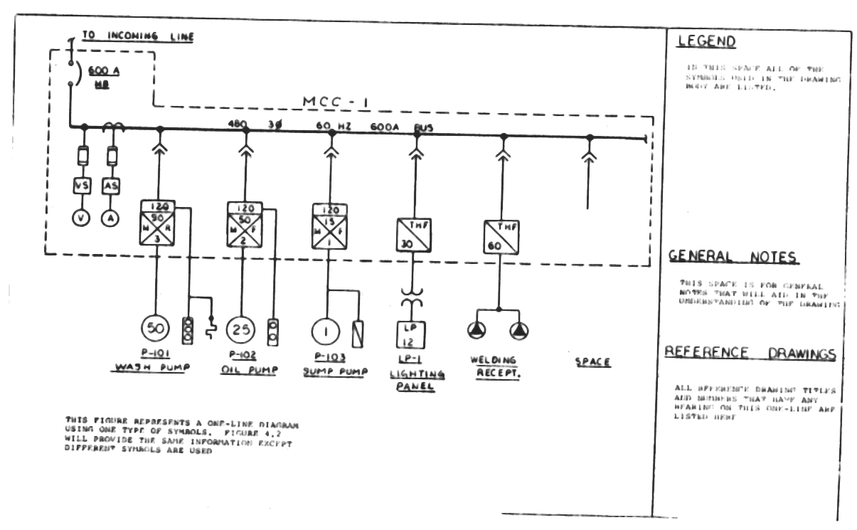
Different types of electrical drawings are used in working with motors and their control circuits.
Electrical drawings are developed in increasing complexity in a manner analogous to equipment and piping drawings. 1 electrical outlines and different kinds of drawings. A single line can show all or part of a system. This enables the user to place two different representations down of the same component. This can be used by architects and engineers. A second rule for drawing electric field lines involves drawing the lines of force perpendicular to the surfaces of objects at the locations where the lines connect to object's surfaces. Different types of electrical drawings are used in working with motors and their control circuits. In the single line diagram, the system component is usually drawn in the form of their symbols. Single line diagram is the representation of a power system using the simple symbol for each component. Then the drawing can be imported, and partially exploded so it becomes revit drafting lines. Such a simplified diagram of an electric power system is called single line diagram of electrical system. To read and interpret electrical diagrams and schematics, the basic symbols and conventions used in the drawing must be understood. Use line hops if any lines need to cross.
This would lead to the occurrence of an electric current within the object; This is true at both big and small scales: Among these you'll find commonly used electrical drawings and schematics, like circuit diagrams, wiring diagrams, electrical plans and block diagrams. Electrical elements such as circuit breakers, transformers, capacitors, bus bars, and conductors are shown by standardized schematic symbols.instead of representing each of three phases with a separate line or terminal. It is the first step in preparing a critical response plan, allowing you to become thoroughly familiar with the electrical transmission.
Electrical Single-Line Diagram | Intelligent One Line ... from etap.com Draw circuits represented by lines. It is very versatile and comprehensive because it can depict very simple dc circuits, or a very complicated we use universally accepted electrical symbols to represent the different electrical components and their relationship within a circuit or system. Lighting plans, outdoor & indoor. It is the first step in preparing a critical response plan, allowing you to become thoroughly familiar with the electrical transmission. Use line hops if any lines need to cross. 1 electrical outlines and different kinds of drawings. In order to facilitate making and reading electrical drawings, certain standard. How to draw hvac single line diagram.
In the single line diagram, the system component is usually drawn in the form of their symbols.
This is true at both big and small scales: Generator and transformer connections, star, delta and neutral earthing are indicated. In the single line diagram, the system component is usually drawn in the form of their symbols. Use line hops if any lines need to cross. Electrical elements such as circuit breakers, transformers, capacitors, bus bars, and conductors are shown by standardized schematic symbols.instead of representing each of three phases with a separate line or terminal. This enables the user to place two different representations down of the same component. In order to facilitate making and reading electrical drawings, certain standard. Typical electrical drawing symbols and. To read and interpret electrical diagrams and schematics, the basic symbols and conventions used in the drawing must be understood. It is the first step in preparing a critical response plan, allowing you to become thoroughly familiar with the electrical transmission. Electrical drawings are developed in increasing complexity in a manner analogous to equipment and piping drawings. Electrical diagrams and schematics, electrical single line diagram, motor symbols, fuse symbols, circuit breaker symbols, generator symbols. 1 electrical outlines and different kinds of drawings.
You have just read the article entitled Single Line Drawing Electrical : Flowtronix (Pvt.) Ltd. - Electrical, Instrumentation and ... / How to draw hvac single line diagram.. You can also bookmark this page with the URL : https://bart-dd.blogspot.com/2021/06/single-line-drawing-electrical.html
Share Awesome
Belum ada Komentar untuk "Single Line Drawing Electrical : Flowtronix (Pvt.) Ltd. - Electrical, Instrumentation and ... / How to draw hvac single line diagram."

Belum ada Komentar untuk "Single Line Drawing Electrical : Flowtronix (Pvt.) Ltd. - Electrical, Instrumentation and ... / How to draw hvac single line diagram."
Posting Komentar